Routing protocols are used to automatically and dynamically exchange routing information between routers. There are several routing protocols to choose from, each with its own pros and cons, as each routing protocol is designed to be well suited to a particular network implementation scenario. Two of the most popular routing protocols used today are Open Shortest Path First (OSPF) and Border Gateway Protocol (BGP). These are very different in their design, as we shall see. We’ll start with a summarized version of the differences and then explain each protocol separately in more depth.
OSPF
OSPF is an interior gateway protocol (IGP) that can route packets inside a single Autonomous System (AS). Unlike other IGPs, OSPF is a link-state routing protocol. In other words, it relies on link-state information to calculate route paths and make routing decisions.
After the protocol starts, each router running OSPF sends link-state advertisements (LSAs) throughout the AS or area containing information about its connected interfaces and routing metrics. When there is a change to any of the routers, the change is propagated to all the routers in the area. Such an update triggers a rerun of the shortest-path-first algorithm.
OSPF splits each AS into smaller sections called areas. All the routers in the same area have identical LSA databases. They also have summarized information about the other areas. There are multiple types of OSPF areas, which will be described later in this article.
BGP
BGP is a routing protocol primarily used to perform inter-domain routing, and is considered an External Gateway Protocol (EGP). However, BGP can also be used to advertise networks within an AS, and when configured to do so, can also function in a similar manner to IGPs.
BGP is used to exchange routing information among routers in the same AS or different ASs. An AS is a set of routers under a single administrative authority. An AS path is the route to a destination. It is also a list of ASs that the route passes through to reach a particular router. Each route has additional information attached that comes in the form of path attributes. The path attributes are used in routing policies to influence how the router routes the traffic.
Summary of differences between OSPF and BGP
Below is a summary of some of the differences between OSPF and BGP.
Differences between OSPF and BGP
There are a number of differences between OSPF and BGP. To start with, OSPF is an interior gateway protocol. Therefore, it is confined to a single domain for routing (intra-domain). On the other hand, BGP is primarily designed to be used to route between routing domains (inter-domain).
OSPF can be successfully deployed in networks with several hundred routers in a single flat area. However, this is in direct relation to the resources available on the routers (read below about the resource requirements). Conversely, the only routing protocol that runs on the Internet exclusively is BGP.
Basic configuration of OSPF (say a single area with no fancy features deployed) is relatively easy. Even the most basic BGP configuration requires more effort than OSPF’s basic configuration (and some advanced routing knowledge). While both OSPF and BGP can get very complex, BGP is far more difficult to use due to numerous available features that make it suitable in many situations and corner cases. For example, OSPF primarily focuses on the metric to determine the best route. BGP on the other hand uses a series of attributes that can be adjusted very granularly, to modify routing behavior in multiple ways.
OSPF must be deployed hierarchically (we will discuss this in the next section), whereas BGP does not require any hierarchy to scale.
In terms of convergence, OSPF reacts faster to network changes than BGP. This makes sense, given that BGP is designed for vast networks where changes happen more often statistically. You would not want routers on large networks to be constantly recalculating routes.
As for resource requirements, because OSPF requires constant calculation, it is considered CPU- and memory-intensive. In contrast, BGP does not react that quickly but becomes CPU- and memory-intensive when the size of the routing table increases. Therefore, routers holding the Internet routing table require powerful CPUs and lots of memory.
Regarding the metric used to calculate the best route, OSPF uses cost, derived from interface bandwidth plus the cost advertised by the other routers when the LSA is sent. BGP can use any BGP attributes to select the best route.
The inner workings of OSPF and BGP
This section describes the two protocols in more detail. We will focus on the most common options that we will see configured in the article’s next section.
OSPF
As mentioned in the first section, OSPF is a link-state routing protocol. OSPF routers exchange link-state advertisements that describe networks they know. From these advertisements, each OSPF router builds within its memory a full topology of the network. Before doing this, though, they need to establish an adjacency with neighboring OSPF routers. Before establishing an adjacency, the two routers must become neighbors. The routers find each other using Hello packets.
The following information from the Hello packets sent by the two routers must match:
- They should be in the same area.
- The router ID must be unique.
- The subnet must be the same.
- The Hello and dead timer must be the same.
- The stub flag must match.
- The authentication must match.
It’s important to know that not all neighbor routers become adjacent as well. Let’s consider the scenario in Figure 1 (a broadcast or a nonbroadcast multiaccess network).

The OSPF Hello protocol will elect a designated router (DR) for the network in this particular example. For redundancy purposes, a backup designated router (BDR) will be elected. Every other router from the segment will become a DROther. This means that the DROther will become adjacent only with the DR and BDR, and every DROther router will receive the LSA from the DR (or BDR, in case the DR fails).
The purpose of this mechanism is to reduce the amount of routing information traffic exchanged. There are two rules to elect the DR and BDR:
- Priority: Highest priority is preferred.
- Router ID: Highest router ID is preferred.
The router ID is derived using the following options:
- Manually set.
- The highest IP address from a loopback interface.
- The highest IP address from an up physical interface.
Should every OSPF configuration be left at default and all the routers be configured at exactly the exact moment, in the above case, R3 will become the DR, R2 the BDR, and R1 the DROther (Figure 2).

Above, the DROther sends its updates to the multicast IP address 224.0.0.6, on which only the DR and BDR are listening. The DR sends the update to 224.0.0.5, to which all the routers from the segment are listening.
It was mentioned that OSPF was designed to be hierarchical to scale, which is achieved by using OSPF areas. Based on the type of LSAs that can be present in an area, these are the OSPF areas:
It is worthwhile to discuss what each LSA type is:
- LSA Type 1 - Router LSA: Generated by every router and describes the router links.
- LSA Type 2 - Network LSA: Generated by the DR and describes the routers connected to the segment.
- LSA Type 3 - Network Summary LSA: Generated by the Area Border Router and sent to another area to represent the destinations outside that area.
- LSA Type 4 - ASBR Summary: Used to describe the router that advertises external routes.
- LSA Type 5 - AS External LSA: Represents the routes external to the AS.
- LSA Type 7 - NSSA External: Represents the external routes from an NSSA area that will be converted to Type 5 LSA.
Now let’s discuss the router types in OSPF, as shown in Figure 3.
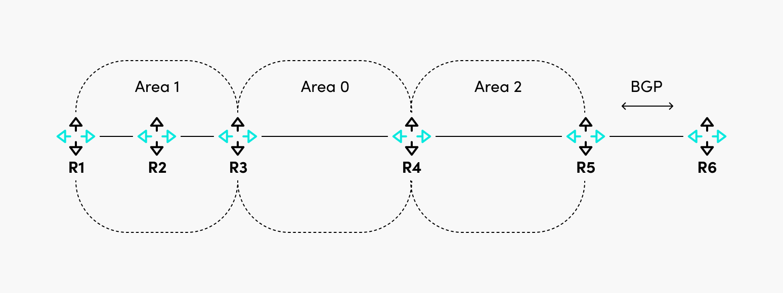
In this particular case, area 0 is the backbone area, the rest of the areas are non-backbone areas, and these are the roles of the routers:
- R1 and R2: Internal routers because all their interfaces are in the same area.
- R3 and R4: Area Border Routers because their interfaces are in two different areas. They are also called backbone routers because they have at least one interface in Area 0.
- R5: Autonomous System Border Router, which redistributes external routes (BGP) in OSPF.
BGP
As already mentioned, BGP is used to connect ASes or to advertise network reachability information inside an AS.
When BGP is configured between routers in the same AS, it is called Internal BGP. When it is configured between routers in different ASes, it is called External BGP (Figure 4).

In this example, between R1 and R2, the BGP session is internal, and between R2 and R3, the BGP session is external. The network reachability information is sent through BGP Update messages, allowing the routes’ advertisement and withdrawal.
One of the most critical fields in the Update message is the “Path Attributes,” which define what attributes are attached to the routes. There are four categories of BGP attributes:
- Well-Known Mandatory: These are recognized by all BGP speakers and must be present in all Update messages.
- Well-Known Discretionary: All BGP speakers recognize these messages, but they can optionally be present in Update messages.
- Optional Transitive: These may or may not be recognized by BGP speakers, but even so, they are passed to other BGP peers.
- Optional Non-Transitive: The BGP speakers might recognize these messages but not pass them to other BGP peers.
While OSPF uses cost as a metric to determine the best path, BGP uses BGP attributes to determine the best path. Because it is not uncommon to have multiple paths to the same destination, BGP has a best-path selection algorithm to eventually choose the best path (or paths, if BGP multipath is configured).
Detailed information about the exact steps for the algorithm are described here and here.
One thing to remember is that a route will be considered suitable as a candidate for the best path only if the next hop to reach that route is reachable.
Consider Figure 5. By default, if no additional actions are taken on R2, R1 will not accept the 10.10.10.0/24 route because, in the BGP Update message, the next hop for the route is R3, and R1 does not know how to reach it.

There are multiple ways to solve the problem above, and they are listed below:
- R2 can set itself as the next-hop-self for the BGP update sent to R1, so R1 now has the next-hop IP address within its routing table.
- R2 can advertise the subnet between R2 and R3 in the IGP of AS 1. This however, is less desirable, since inter AS communication should be restricted only to BGP, otherwise unpredictable routing may occur. It is best practice to keep IGPs operating within the boundaries of their ASes.
{{banner-8="/design/banners"}}
Configuration
This section shows how to configure basic OSPF and BGP on Cisco routers.
OSPF
For OSPF, we will use the following diagram of a multi-area OSPF network. In this scenario, R3 is the ABR because it has interfaces in both Area 0 and Area 1. Area 1 is a non-backbone area (not a stub, stubby, or NSSA).

Following interface configuration, this is what is required on R1 to be configured as an internal backbone router (the same configuration is done for R2 with the difference of IP addressing).
router ospf 1
 network 1.1.1.1 0.0.0.0 area 0
 network 10.10.10.1 0.0.0.0 area 0
The configuration is similar for R4, except that the interfaces are added in Area 1.
R3 has a different configuration. Observe how interfaces are part of different areas.
router ospf 1
 network 1.1.1.3 0.0.0.0 area 0
 network 10.10.10.3 0.0.0.0 area 0
 network 20.20.20.3 0.0.0.0 area 1
Because all three routers in Area 0 were configured simultaneously and none of the OSPF parameters were changed, R3 became the DR, R2 became the BDR, and R1 became DROther. As mentioned before, the router ID of R3 was the highest because it has the highest loopback IP address out of the three routers in Area 0.
R1#show ip ospf neighbor Ethernet0/0

Neighbor ID     Pri   State           Dead Time   Address         Interface
1.1.1.2           1   FULL/BDR        00:00:32    10.10.10.2      Ethernet0/0
1.1.1.3           1   FULL/DR         00:00:39    10.10.10.3      Ethernet0/0
R1#
If you checked on R3, R1 would be in the state of DROther.
R3#show ip ospf neighbor Ethernet0/0

Neighbor ID     Pri   State           Dead Time   Address         Interface
1.1.1.1           1   FULL/DROTHER    00:00:35    10.10.10.1      Ethernet0/0
1.1.1.2           1   FULL/BDR        00:00:31    10.10.10.2      Ethernet0/0
R3#
Checking the routing table of R1, you would see routes from the same area (Area 0) and Area 1 (with the code of IA).
1.0.0.0/32 is subnetted, 4 subnets
O        1.1.1.2 [110/11] via 10.10.10.2, 00:06:55, Ethernet0/0
O        1.1.1.3 [110/11] via 10.10.10.3, 00:06:55, Ethernet0/0
O IA     1.1.1.4 [110/21] via 10.10.10.3, 00:06:55, Ethernet0/0
      20.0.0.0/24 is subnetted, 1 subnets
O IA     20.20.20.0 [110/20] via 10.10.10.3, 00:06:55, Ethernet0/0
This would be a basic configuration of a multi-area OSPF network. This kind of deployment will suffice for most networks.
BGP
For BGP, we will use the setup in Figure 7.

R1 and R2 are in AS1 (which means they will have an internal BGP between them), and R3 is in AS 2, so there will be an external BGP session between R2 and R3. R3 advertises the route for 1.1.1.1/32.
The configuration required for R1 is the one below.
router bgp 1
 neighbor 10.10.10.2 remote-as 1
The configuration for R2 is the one below.
router bgp 1
 neighbor 10.10.10.1 remote-as 1
 neighbor 20.20.20.3 remote-as 2
And the configuration for R3. There is an additional command required to advertise the network 1.1.1.1/32, as noted below.
router bgp 2
 network 1.1.1.1 mask 255.255.255.255
 neighbor 20.20.20.2 remote-as 1
At this point, R2 should have in its routing table the network 1.1.1.1/32, but R1 will not have it because the next hop of the route (20.20.20.3) is not reachable by R1.
R1#show ip route bgp

Gateway of last resort is not set

R1#sh ip bgp 1.1.1.1
BGP routing table entry for 1.1.1.1/32, version 0
Paths: (1 available, no best path)
  Not advertised to any peer
  Refresh Epoch 1
  2
    20.20.20.3 (inaccessible) from 10.10.10.2 (10.10.10.2)
      Origin IGP, metric 0, localpref 100, valid, internal
      rx pathid: 0, tx pathid: 0
R1#
To solve this, we can configure R2 to set itself as the next-hop for the routes it advertises to R1.
router bgp 1
 neighbor 10.10.10.1 remote-as 1
 neighbor 10.10.10.1 next-hop-self
 neighbor 20.20.20.3 remote-as 2
This will allow R1 to install the route in the routing table.
Gateway of last resort is not set

      1.0.0.0/32 is subnetted, 1 subnets
B        1.1.1.1 [200/0] via 10.10.10.2, 00:00:25
R1#
At first sight, the BGP configuration is simple, but this is as basic as it can get. In real life, one would need to play around with BGP attribute manipulation and configure additional features. Some of the attributes that can be manipulated to affect BGP routing behavior include Local Preference, AS_PATH length, and MED to name a few. The BGP configuration can get very complex, and vendors constantly add new complex features to support more and more use cases.
{{banner-sre="/design/banners"}}
Conclusion
The following are lists that summarize the pros and cons of each routing protocol. Note that some of the cons may not actually be considered cons in certain situations, so these should be taken only as guidelines.
OSPF
- Prossome text
- Fast convergence
- Open standard
- Scalable due to hierarchical area implementation
- Conssome text
- Uses large amounts of system resources (CPU, memory) to run algorithm and maintain full network topology information
- Multiple area types and link state advertisement types can become extensively complex
BGP
- Prossome text
- Extremely scalable
- Low resource usage even for large BGP tables
- Extremely granular routing behavior adjustments
- Conssome text
- Slow to converge
- Complexity can increase if many BGP attributes are tweaked
BGP and OSPF are complex protocols. Their configuration can get very difficult sometimes, and it is critical to understand how the protocols work and what their core components are. Failing to do so would not only prevent you from having the right configuration, but also put you at risk of not being able to properly troubleshoot any issues with these protocols.
It is also worth checking the latest vendor documentation regarding features and their configuration, because the defaults of each feature might change from release to release.

