Switching loops occur when network switches are connected together in such a way that network traffic loops around infinitely instead of traversing the hops needed to travel from source to destination.
They are a thorn in the side of any network administrator. They can take down an entire network and are difficult to trace back to the source of the problem. Fortunately, there are protocols that can be implemented to prevent them. This article will explain what causes switching loops, how to trace their source, and how to prevent them from occurring.
Switching 101
To understand what a switching loop is and how it happens, it’s necessary to have a basic grasp of network switching.
Network switches are the backbone of the local area network (LAN). Switches work at Layer 2 of the OSI model, meaning they deal in forwarding traffic based on MAC addresses. MAC addresses are unique hardware addresses that are encoded within a network interface on a device. They are written in hexadecimal format and have values that range from 00:00:00:00:00:00 through FF:FF:FF:FF:FF:FF.
MAC addresses are basically like people’s names. They rarely change, and you can use them to address an individual device. Switches and network devices also have special reserved MAC addresses used to address all devices on the network. The real-life equivalent would be saying “hey everyone” to address a group of people as opposed to using each of their individual names. With networking, “everyone” is the broadcast MAC address, which is FF:FF:FF:FF:FF:FF.
Switches work by learning the MAC addresses of all connected devices and forwarding traffic received from any transmitting device to only the device it is addressed to, based on the destination MAC address. This ensures that unnecessary traffic and broadcasts are minimized, which preserves network bandwidth and improves performance.
There are a couple of special cases. When a switch receives traffic targeted to a broadcast or multicast MAC address, it floods the traffic out all ports to the broadcast address except for the port the traffic was received on. Also, when a switch receives traffic destined for a MAC address that it does not know, it will flood traffic to the broadcast address on all ports except the one from which it was received.
How loops happen
During normal operation, switches forward traffic along a path from one destination to another hop by hop. However, when switches are connected in such a way that it creates a loop, network traffic can get stuck in this loop and never reach its destination.
Additionally, because of the nature of how switches function by default in forwarding broadcast and multicast frames out all ports, this can lead to a broadcast storm that loops infinitely. The result is a network outage, as the traffic volume in the loop grows and grows until it overwhelms all the switches’ capacities in the loop’s path.
Loops can occur because someone accidentally physically loops an ethernet cable to two ports on the same switch (good cable management helps here!). A loop can also form when a switch is intentionally connected via two uplinks to another switch for redundancy, if the proper configuration isn’t in place to logically prevent a loop.
Figure 1 shows an instance of a loop between Switch A and Switch B. Under normal circumstances, broadcasts would not flow in a loop because there would be no loop. However, introducing a loop between Switch A and Switch B causes a broadcast storm as the broadcast traffic keeps circulating and duplicating itself until the switches are overwhelmed.

Troubleshooting a switching loop
Although protocols exist to help prevent switching loops, they are not always implemented. When they are, they are sometimes not implemented correctly. As a result, knowing how to trace the source of a loop manually is a good skill for an administrator to have. The diagram below shows a basic example of a network with a switching loop introduced, in this case, between Switch C and Switch D, which have two connections.

If you suspect a switching loop and part or all of the network is down, you should take the following steps to troubleshoot and trace the source:
1. Rule out other potential sources of an outage, like DNS issues, hardware failure, etc.
2. Note the network topology: single L2 switch, multiple L2 switches connected to a core switch, etc.
3. Start at the top of the network switching hierarchy where the loop is affecting network connectivity, for example, at the core switch in the diagram above. Then connect a laptop to the switch you determined to be the top of the hierarchy affected by the loop.
4. Start a continuous ping session to a device on your network with the command ping (IP Address) -t
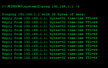
5. Pay attention to the ping session time: If a loop has happened, the ping time should increase dramatically as the broadcast storm overwhelms the network.

6. While continuing the ping session, unplug each uplinked switch from the core, or each device from an access layer switch, if starting there.
7. Monitor the ping session after each uplink is disconnected for 30 seconds to see if the time decreases and normal network connectivity returns.
8. Once you see normal network connectivity return, you have narrowed down the source of the loop. In the case of Figure 2, after disconnecting the uplink to Switch C, the loop would go away and normal network connectivity would be restored.
9. Once you have found the source of the loop, disconnect it to remove the loop.
{{banner-3="/design/banners"}}
Preventing switching loops
As the saying goes, “an ounce of prevention is worth a pound of cure.” Knowing how to identify the source of a switching loop is a good skill to have, but ideally, a network administrator will want to leverage protocols and technologies that prevent switching loops from occurring.
Spanning Tree Protocol
The gold standard for preventing switching loops is the Spanning Tree Protocol (STP). It works by creating a group of switches that exchange information via special frames called bridge protocol data units (BPDUs) to create and maintain a loop-free topology.
Whenever a loop is detected, the switches will share information with each other via the BPDUs and select a port implicated in the loop to place into a blocking state based on lowest-cost path metrics. This effectively logically deactivates whatever links are necessary to keep the network loop-free.
STP has several different modes, like Per-VLAN Spanning Tree (PVST) and rapid-PVST. PVST is usually the default setting that runs spanning tree on any specified VLAN. Rapid-PVST is essentially the same as PVST, but with faster convergence time. The main objective they accomplish is the same: preventing switching loops.
Here’s an example of how to configure STP on a switch.
- From the switch CLI, enter enable mode.

- Enter config mode.

- Enable spanning-tree globally on the switch.

Best practices
Once configured, the switch will protect the network from loops. However, it is a good idea to follow some additional best practices for optimal results.
First, make sure all switches have STP enabled. That way, loops are prevented across the entire network.
Next, configure STP portfast mode on interfaces that connect to endpoints that should not send BPDUs, like workstations and servers (basically, anything but other switches). This allows ports connected to workstations to become active faster since they can assume that they are not uplinked to another switch. This helps with network connectivity delays when computers are rebooted, etc.
Here’s how to configure portfast mode.
- Select the interface where you want to enable portfast.

- Enable portfast with the command below.

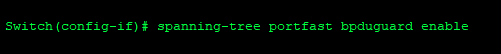
Additionally, it is a good practice to configure BPDU guard on interfaces that are set as spanning-tree portfast. BPDU guard will detect BPDU frames, presumably from a rogue switch being uplinked, and disable the port.
Finally, shut down unused ports so connecting a new device requires intervention by an administrator. This will help prevent loops and rogue devices from being connected either accidentally or intentionally.
{{banner-sre="/design/banners"}}
Conclusion
Switching loops can take down an entire network. It is important for network administrators to understand how they happen, because understanding them gives administrators a better grasp of how network traffic flows and the ability to troubleshoot loops to avoid frustration.
Preventing loops should always be the goal. Properly configuring the Spanning Tree Protocol on switches is the standard tool to preemptively stop loops from forming and improve overall network resilience.