A virtual private network (VPN) extends a private network over a public and potentially insecure network. Devices connected to each other over a VPN can share information as if they were directly connected to the same private network.
The most common implementation of VPNs delivers remote, secure, and confidential connectivity across the public Internet, providing access to resources on a private network that would otherwise be inaccessible via the Internet. As such, the most common use for VPNs is to provide network connectivity for remote workers.
VPN mechanisms are employed primarily at Layer 3 of the OSI model (the Network Layer), where packets with private source and destination IP addresses are encapsulated into packets with publicly routable addresses.
During the current time of transitioning from IPv4 to IPv6, VPNs must be able to employ the same security and confidentiality using IPv6 as they have been doing with IPv4. In this article, we'll explore how VPNs function, the role of the IP protocol in their operation, and the implications that the transition to IPv6 has on their implementation.
Executive summary
The following concepts will be explored in the subsequent sections of this article.
Explanations
Types of VPNs: Host-based and site-to-site
VPNs are used to establish a virtual point-to-point connection between either a client and a corporate network or two geographically remote networks, as shown in the following diagram.

In this scenario, we have a remote worker connecting to the VPN server at HQ via VPN client software. Using this method, the remote worker's laptop will obtain an internal IP address on the HQ private network, enjoying the same connectivity to the internal services as the HQ user physically located at HQ. This is known as a host-based VPN connection, where a single host connects to the VPN server located on the HQ premises.
Similarly, the private network of the branch office connects to the VPN server of HQ via a VPN client such as a router or a firewall. This way, all devices on the branch office's private network can connect to the HQ private network. As a result, the branch user will be able to access the same internal services as the HQ user. This VPN scenario is called a site-to-site VPN, because the whole branch site obtains access to the HQ network via the VPN.
{{banner-13="/design/banners"}}
VPN security and confidentiality
Beyond connectivity, a VPN delivers security via authentication and confidentiality through encryption. Authentication ensures that only authorized users and devices can connect to the VPN. As the VPN is established across the insecure internet, it could be subject to interception. Confidentiality is provided by encryption mechanisms, ensuring that unauthorized interceptors can only obtain unintelligible data, and only authorized users and devices can decrypt and view the data properly.
How a VPN works
As mentioned earlier, the mechanisms used to deploy a VPN are implemented primarily within Layer 3 of the OSI model. Refer to the following diagram that describes the encapsulation process as we descend the OSI model layers.
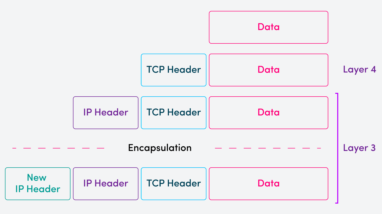
The example above depicts data that is encapsulated into a Layer 4 segment with a TCP header, which is, in turn, encapsulated into a Layer 3 packet with an IP header. This first IP header contains the source and destination IP addresses found within the private network.
When this packet is sent over the VPN, an additional Layer 3 encapsulation takes place with a new IP header prepended to the packet. This new IP header contains the public source and destination IP addresses of the VPN server and VPN client. In this sense, the original IP packet, with private source and destination IP addresses, becomes the payload of the new IP packet with public source and destination IP addresses.
This encapsulation is also called tunneling, which is where the term “VPN tunnel” comes from.
Authentication and confidentiality
Apart from tunneling private data over a public network, VPNs have additional mechanisms that ensure authentication and confidentiality. These are delivered via additional security headers and trailers added during the encapsulation process. This is illustrated below:
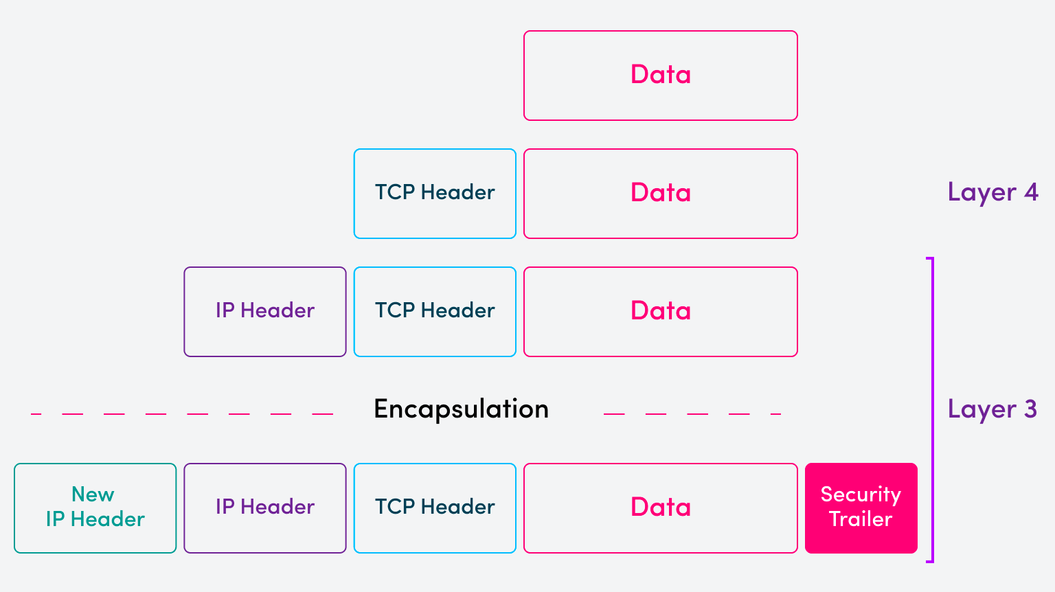
To properly encapsulate the payload packet for transmission over a VPN, encryption and authentication algorithms must be applied before sending it. At the receiving host or network device, these headers and trailers are used to authenticate and decrypt the packet for native forwarding within the private network.
Many different protocol frameworks can be used to implement these security operations, but IPsec is the most widely used protocol framework. For IPv4, IPsec is an add-on protocol, while for IPv6, its mechanisms are built into the protocol itself using extension headers.
{{banner-9="/design/banners"}}
Anatomy of an IPv6 VPN
An IPv6 VPN differs very little fundamentally from an IPv4 VPN. The same encapsulation process that has been described above takes place using the same logic. The differences arise in two primary areas: the addresses used and how encryption and authentication are applied.
In a purely IPv6 environment, where you have IPv6 addresses on the internal private network as well as on the public network (such as the Internet), you would see an IPv6 packet encapsulated within an additional IPv6 header. When viewing a Wireshark capture, you would see something like this:
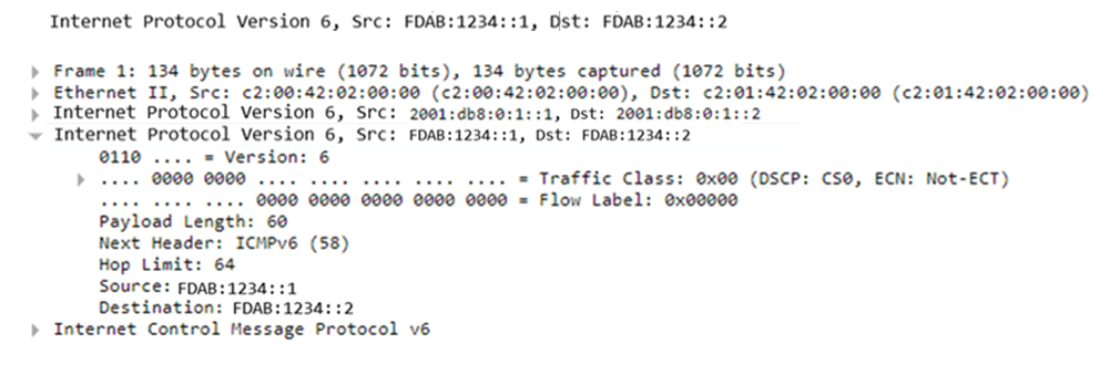
Notice that we have an IPv6 packet with source address FDAB:1234::1. This is a unique local IPv6 address, which is the counterpart of IPv4's private address range. This IPv6 packet is encapsulated within another IPv6 packet with global unicast source and destination addresses.
The example above does not include any security features but simply showcases how IPv6 can be encapsulated into IPv6 in a purely IPv6 environment.
As will be shown in subsequent sections, VPNs can also be used to encapsulate IPv6 in IPv4 as well as IPv4 in IPv6. Such VPNs are useful for environments where both protocols are being used in different areas of the network.
IPv6 VPNs in dual-stack environments
In a dual-stack environment, both IPv4 and IPv6 are used in different parts of the same network. When employed, there are different transition mechanisms that can be used to allow the multiple parts of the network using these protocols to communicate with each other.
Using an IPv6 VPN in this environment can be beneficial. For example, an ISP may be using IPv4 addresses on part of its infrastructure and connecting two disparate portions of its network via a third-party ISP that uses IPv6 infrastructure. For communication to take place between these distinct networks, a VPN can be used where IPv4 packets will be encapsulated within an IPv6 VPN.
Such VPNs also deliver the opposite encapsulation. The following is an example of a Wireshark capture where an IPv6 packet is encapsulated within an IPv4 packet:
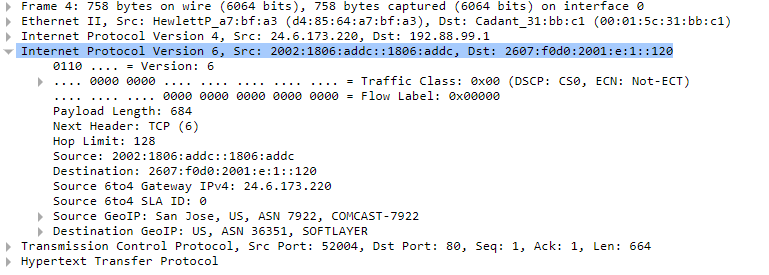
This is a communication with a web server, and you can see that the application layer is using the Hypertext Transfer Protocol (HTTP). The IPv4 source and destination addresses are publicly routed addresses that are used to allow the VPN server and client to communicate. Within that IPv4 packet is an IPv6 packet with the corresponding addresses.
IPv6 VPN configuration example
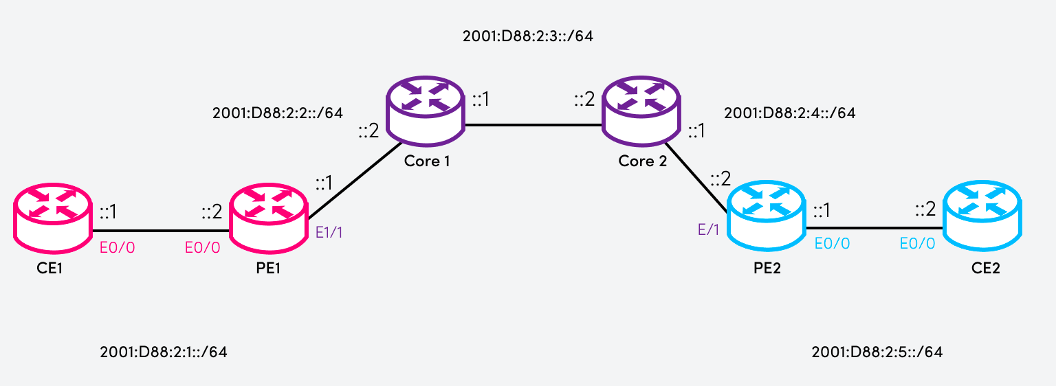
In this example, an IPv6 VPN is deployed on Cisco routers and includes the configuration of these devices to achieve this. We will be using the following topology:
- CE (Customer Equipment) router: The device on the customer's premises, typically owned by the business in question.
- PE (Provider Edge) router: The device delivering the communication service to the customer's premises.
- Core router: A device that comprises part of the core network of the provider.
Imagine that IPv6 routing has been configured correctly on all routers involved. We want to create an IPv6 VPN tunnel between PE1 and PE2 so that the two CE routers can communicate with each other over that VPN.
Our configurations will take place on the PE and CE routers. We will create an IPv6 VPN tunnel with endpoints within the 2001:DB8:2:9::/64 subnet.
{{banner-10="/design/banners"}}
CE router configuration
The following shows the configurations of each CE router. Remember that the CE router is not aware of the IPv6 tunnel, but it must know how to route traffic through that tunnel:
CE1:
CE2:
Notice the following:
- In both cases, we enable IPv6 routing using the ipv6 unicast-routing command.
- We also configure the interface facing each PE router with the appropriate IPv6 address as described in the diagram.
- Finally, we configure static IPv6 routes so that each CE router can reach:
- The network of the other CE router
- The 2001:DB8:2:9::/64 network used by the VPN tunnel
PE router configuration
The following shows the configuration of the PE routers, which are the devices on which the IPv6 VPN terminates.
PE1:
PE2:
Notice the following:
- A tunnel interface is created on each device.
- The tunnels configured on each PE router use the 2001:DB8:2:9::/64 subnet.
- These tunnels are bound to the E1/1 interfaces on both PE routers.
- IPv6 packets sent to the subnets connected to the CE routers are routed via the VPN tunnel.
- IPv6 packets are encapsulated into IPv6 packets with source and destination IPv6 addresses of 2001:DB8:2:9::1 and 2001:DB8:2:9::2, respectively, depending upon the direction of travel.
The IPv6 VPN terminates on the PE nodes, and packets in transit across the provider network are tunneled inside the VPN. All communication between CE1 and CE2 will now be encapsulated into an IPv6 VPN on ingress to the provider network. Communication on the PE-CE link will be via native IP routing.
IPv6 inherent VPN security
When using VPNs in general, security is a primary concern. The example above demonstrates only the tunneling component of the VPN for demonstration purposes.
IPv4 required a separate suite of add-on protocols and mechanisms, typically IPsec, to provide authentication and confidentiality. IPv6 VPNs, however, can enjoy this security as an inherent part of IPv6's architecture. Using the concept of extension headers, IPv6 can add more security functionality and features to its communication by simply adding the appropriate extension header as part of the IPv6 header, which contains all the necessary information to perform encryption, authentication, and more. There are several methods of implementation depending upon the needs of the particular instance.
{{banner-sre="/design/banners"}}
Summary of key concepts
VPNs are constructs that allow the extension of private networks over public network infrastructure in a secure and confidential manner. The primary mechanisms of VPNs take place at Layer 3 of the OSI model, so it is mainly the IPv4 and IPv6 protocols that are involved in the creation of these VPNs by encapsulating the packet containing the private source and destination addresses with another Layer 3 header containing the public routable addresses.
The advent of IPv6 has required VPNs to be able to operate using this new communication protocol and to be able to function in conjunction with existing IPv4 networks. IPv6 VPNs deliver this connectivity using the newer IPv6, with the added benefit of the inherently designed security features of this newer protocol.